How to create a transformer for SEPA using Altova MapForce
jhmase: old client
The purpose with this page is to give a step-by-step guide how to create a
XSL transformer for converting a SEPA based XML layout to another SEPA XML
layout, by using the third part tool Altova Map Force.
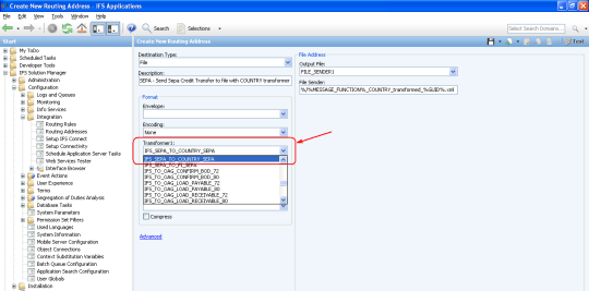
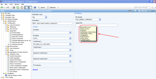
The output XML layout from the BizApi
SEND_SEPA_CREDIT_TRANSFER will be used as source and it will be mapped to
the UNIFI ISO 20022 standard XML layout .
Note: This page can also be used as a general guide on how to
create a XSL transformer with Altova MapForce.
Altova MapForce Standard Edition is a visual
XML-to-XML mapping tool for converting XML data from one format to another XML
format using a simple graphic interface.
Use this page when you need to learn how to create a XSL transformer for a
SEPA specific XML layout.
Contents
- IFS Applications 8
- Altova Map Force Standard Edition
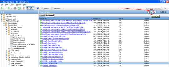
- Open IFS Solution Manager
- Navigate to Configuration / Integration /
Interface Browser / By Type / Bizapi's
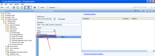
- Select the Bizapi SEND_SEPA_CREDIT_TRANSFER

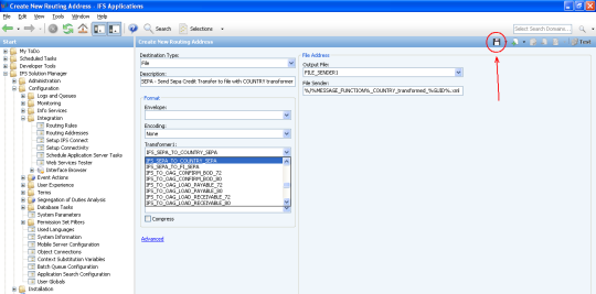
- Press the down-arrow button next to General
Information in the menu bar.
- Select the menu item Request XSD Schema.
- Select Save As in the menu bar and save
the XSD Schema file somewhere on your disk where you can find it later.
- Press the down arrow button next to Request
XSD Schema in the menu bar.
- Select the menu item Request XML sample.
- Select Save As in the menu bar and save
the XML sample file in the same place as the XSD Schema file.
Now the source XML schema file is available.
Next step is to obtain a
target schema file for the Customer Credit Transfer message from the
UNIFI ISO 20022 standard homepage.
- Download the UNIFI ISO 20022 standard XML Schema file (Msg ID
pain.001.001.02) and example XML file (XML Instances) from www.iso20022.org
> Catalogue of UNIFI Messages > Payments > Payment Inititation >
CustomerCreditTransferInitiationV02 (http://www.iso20022.org/index.cfm?item_id=59950#PaymentsInitiation).
Note that both of the zip-files are named
pain.001.001.02.zip, so you have to rename the first downloaded
zip-file before downloading the second one.
- Unzip the files to the same place as the previously saved files from IFS
Connect.

- Start Altova MapForce and select
Insert XML Schema/File in the menu bar.
- Navigate to the place where you have saved all the files above.
- Open the Request XSD Schema file
generated from IFS Connect
- In the following dialog window press Yes
and select the Request XML sample file
generated from IFS Connect.
- Do the same procedure with the UNIFI ISO 20022
standard files (or your country specific target files).
First press Insert XML Schema/File in
the menu bar, select pain.001.001.02.xsd, answer
Yes in the dialog window and select the
pain.001.001.02.xml file. The window will
show something like the following,
- Next you have to initially map the structure to ensure that the
aggregation levels of the IFS structure matches with the ISO structure
levels. Expand the SEPA_HEADER node and the
pain.001.001.02 node.
- Connect the SEPA_HEADER node with the
GrpHdr node by drawing a line between the
arrow to the right of SEPA_HEADER and the
arrow to the left of GrpHdr.

- Expand the PAYMENTS node and the
PmtInf node.
- Connect the SEPA_PAYMENT node with the
PmtInf node by drawing a line between the
arrow to the right of SEPA_PAYMENT and the
arrow to the left of PmtInf.

- Expand the TRANSES node and the
CdtTrfTxInf node.
- Connect the SEPA_PAYMENT_TRANS node
with the CdtTrfTxInf node by drawing a line
between the arrow to the right of
SEPA_PAYMENT_TRANS and the arrow to the left of
CdtTrfTxInf.

- Now the aggregation levels of the IFS structure matches with the ISO
structure levels and it is time to map all nodes that should exist in the
final output.
- You can whenever you want validate the mapping and, if there are no
errors, check the output by selecting the Output
tab.

- When you are finished mapping and want to save the transformer, select
the File menu and menu item
Generate code in XSLT 1.0.

- Choose where to save the files.
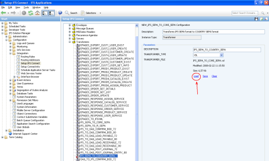
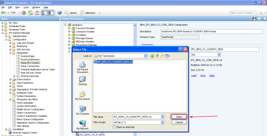
The result is two files; one .bat-file and one .xslt-file. The xslt-file
is the one that contains the transformer and is to be imported into IFS
Connect, but before you import it you should rename the extension of the
xslt-file to .xsl to follow the IFS naming standard.
This section will give some examples of common situations where it is
beneficial to use constants, functions and filters to achieve a desired layout.
Note: Examples were created by using Altova MapForce Standard Edition version 2007 SP2.
There could be a need of hiding empty nodes in the output XML file and only
show the nodes that contains a value. This can be accomplished by inserting a
constant, a logical function and a filter.
- Insert a constant that contains a NULL
value by selecting Insert constant in the
menu bar, choose radio button All other in
the dialog window and press OK

- Open menu View and select menu item
Library Window.

-
Under the section logical functions, select
function equal and drag it into the mapping
window.

- Close the library window.
- Select Insert Filter in the menu bar

- f you for example want the CdtrRef node
to be visible in the output only when the node
STRUCT_INFO contains a value you can draw the connections like the
figure shows below.
- Draw a line from the NULL constant to one of the inputs of the
function equal
- Draw a line from the node STRUCT_INFO
to the other input of the function equal
- Draw a line from the result output
of the function equal to the
bool input of the filter
- Draw a line from the node STRUCT_INFO
to the node/row input of the filter.
- Draw a line from the on-false
output of the filter to the CdtrRef
node.
- If you also want the whole Strd
node and all of it’s including nodes to be visible in the output only
when the node STRUCT_INFO contains a
value, draw a line from the on-false
output of the filter to the Strd node

The letters indicate the order to add the
transformation instructions
If you want only a part of a node value to be visible in the output you can
use the string-function substring. In this
example we will show how to remove parts of the value for the node
PAYMENT_DATE. The value is presented with both
date and time as 2008-03-11T09:01:01 and we
want to output just the date as 2008-03-11 to
the node ReqdExctnDt
- Insert a constant with the numeric value 1
- Insert another constant in the same way with the numeric value
10
- Open menu View and select menu item
Library Window.
- Under the section string functions,
select function substring and drag it into
the mapping window.
- Draw the connections like the figure shows below
- Draw a line from the node PAYMENT_DATE
to the string input of the function
substring
- Draw a line from the constant 1 to
the start input of the function
substring
- Draw a line from the constant 10 to
the length input of the function
substring.
- Draw a line from the result output
of the function substring to the node
ReqdExctnDt.

The letters indicate the order to add the
transformation instructions
If you want to format a numeric value, for example remove decimals, you can
use the xslt-function format-number.
In this example we will remove the decimal for the node
NO_OF_TRANS. The value of
NO_OF_TRANS is originally presented as for
example 3.0 but in the output we want it to be
presented as 3.
- Insert a constant with the string value #.
-
Open menu View and select menu item
Library Window
- Under the section xslt functions,
select function format-number and drag it
into the mapping window.
- Close the library window
- Draw the connections like the figure shows below.
- Draw a line from the node NO_OF_TRANS
to the value input of the function
format-number.
- Draw a line from the constant # to
the “format” input of the function
format-number.
- Draw a line from the result output
of the function format-number to the
node NbOfTxs.

The letters indicate the order to add the
transformation instructions


